
Georeference a map dwg / dgn
 We will use this exercise to explain some doubts along the way as to how to assign projection to a CAD map.
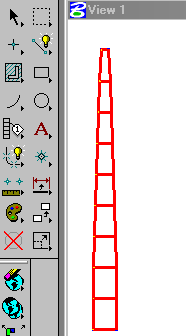
We will use the example Previously built, in which we create a UTM mesh of the 16 north zone from an excel sheet and build with AutoCAD.
1. The units.
This is the main problem when working with a conventional CAD tool. In the case of AutoCAD, the units of work are complex to handle for mere mortals, because when it is installed for the first time and executed, it asks: Are you a gringo? Well, it is not so crude but it asks if it will use units in millimeters or in inches.
The issue is that our Hispanic countries the unit is the meter, so that we can become complicated the world that for purposes of constructive plans is not significant (units are units) ... with some insignificance when loading blocks or styles of line require re-scaling. And although the recent versions of AutoCAD help with this problem, the files made with previous versions maintain the problem of the units for when they want to georeference.
In the case of Microstation, this is configured in the “Working units” but in the same way they continue to be cad files without georeference. You have better control over what Microstation recognizes as a seed file (Seed file), where all those configurations are specified ... that although they are a can understand them at the beginning they help much more than the templates of AutoCAD to the Anglo-Saxon.
Let's remember that if you are working with UTM coordinates, and the map is "georeferenced" to one of those coordinates, what you have is a file with a relative reference to a grid, but it does not yet have a projection or Datum, which is what it is used for. Known as a georeference or absolute reference.

In my case, “so as not to get complicated” with the AutoCAD units, what I do is open a map of my country in Microstation, which I know is georeferenced, I call the AutoCAD file as reference (because it does not require import) and select the button “DWG Options” Where I specify that the work units are “seed file master units”, And above all the Attachment Method that is 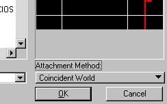 “Coincidence World”. And it does not matter if the dwg was working in millimeters or inches, the file recognizes the working units of my dgn map, then I copy the reference map to my file and save it with another name, that way I know that Map has the characteristics of my seed file.
... okay, it's my complication but it works for me ... you can look for your own perversion
2. Assign Projection
The following is simple, you can do both with manifold, Although if you have a parrot in the back that is worth $ 1,500 you can do it also with ArcGIS So does Map3D, Microstation Geographics, CadCorp...
To do it with Manifold you create a new file, then import the CAD file “File / import / drawing“, you choose the “dgn” file option. It asks you for a choice for curve segments, to which you accept the value that comes by default.

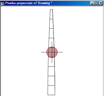
Then the imported file, I delete a point and two lines that I don't know why they are created. For that you just do "Touch and delete“… you play then and delete with the “delete” key 🙂
To assign projection, select the component, right mouse button and choose “assign projection”

Remember that you cannot choose "change projection" because it is a cad file, which does not have a projection.
In my case I will choose “Universal Traverso Mercator”, Zone 16 Northern Hemisphere and WGS84 as Datum.

3 Export it to Google Earth.
This is a good way to check that the map is well georeferenced, so I'll export it to kml (no need to assign it a geographic coordinate projection). Right-click on the already georeferenced component and choose the "export" option, choosing the kml format.
To create the different zones, you only copy the component (without georeference), then paste, paste, paste, paste, paste, paste, paste ... then assign different zones to each component created. (Component in Manifold is equivalent of layer)
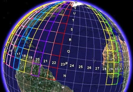
Then you open the kml files with Google Earth, you change the thickness and color of the line ... and there you have the zones from Mexico to Venezuela and those of Spain.
From here you can download the files of this exercise in formats.dwg,.Days V7,.map Of manifold and.kml With the zones utm of the northern hemisphere of the Hispanic countries, including the three that apply to Spain
... all taken from a simple dwg file Built with Excel.


Dear on the subject, I have a doubt and an unresolved problem.
It turns out that I have a CAD file DWG, which has the northern province of Ecuador, said mapita parce be in the 18N Wgs84 area checking coordinates of certain points taken in Google Earth, of course the extension of the map is in the 17 and 18 zones and the northern and southern hemisphere, that's the problem I have a data of an area (polygon) and Shape format with geographical projection Wgs84 which shows me everything correctly in the programs that use projection, but when exporting it to Dwg it bounces me far being that when reviewing the previous coordinates of the north 18 zone in utm of a higher corner that gives in the northern hemisphere I bounce away and the coordinates are not the same and tested with different projections but none gives me but I emphasize according to control coordinates revised in several programs it indicates that the autocad plane is projected in zone 18 north wgs84.
Which may be what I am not taking into account or how I should treat the information in these case.
Thanks in advance for the answer.
You're right, I've already corrected the problem. Check if you can download them
Good.
When clicking on the links, a CPanel screen appears to place name and password and the files are not downloaded ...
http://geofumadas.com/georeferenciar-un-mapa-dwg-dgn/