
More than 60 Autolisp routines for AutoCAD
Lisp for conversions and operations
1. Convert feet to meters and vice versa
This routine generated with Autolisp, allows us to convert the value entered from feet to meters and vice versa, the result is shown in the command line.
 Here we also use the CVunit function, this lisp function, get the conversion values, from the acad.unt file (AutoCAD Unit Definition), if you want to see in detail what these values are and the different types of conversion, I advise you to see this file .
To use this routine, you must do the following:
- Load the lisp file in AutoCAD.
- Enter the name of the command: At the moment, we are already using PIM
- Choose the conversion type: feet to meters or meters to feet
- Enter the value you want to convert
- You will get in the command line the information with the unit conversion
You can get the routine here
2. Multiplies all selected texts
This routine generated in AutoLisp allows to obtain the multiplication of all the values of the selected texts, for this routine to work correctly it is necessary that the selected texts are of type TEXT and not of type MTEXT.

For example, if you have 3 three texts each with the values: 1, 2, 3 and all three are selected, the result of the command will be the multiplication of these three numbers, which will be equal to: 6.
To use this routine, you must do the following:
- Load the lisp file in AutoCAD.
- Enter the name of the command: mul
- Select all the texts that you want to obtain multiplication.
- Press the key Enter To get the result.
You can get the routine here
3. Convert inches to meters
This small routine allows us to convert the value entered in inches to meters showing the result in the command line, also shows the result divided between 2 as part of additional information.
 You can modify this command to convert other types of units, for this you must modify the source code, for example, convert inches to centimeters o Minutes to seconds, Just change the parameters of the function cvunit“, in this command cvunit has the following parameters: “inches” “meters”, with these parameters, the entered value will be taken as inches (inches) and will be converted to meters (meters), you can change the parameters to the following: “ minute” “second”, “inch” “cm”, “acre” “sq yard”, “ft” “in”, among others.
To use this routine, you must do the following:
- Load the lisp file in AutoCAD.
- Enter the name of the command: PM
- Enter the value you want to convert from inches to meters and
Ready, you will get the information with the unit conversion.
You can get the routine here
4. Add the lengths of the lines of the selected layer
 This routine allows you to add the distances of all the lines that are contained in the layer of the object you select.
This routine allows you to add the distances of all the lines that are contained in the layer of the object that you select, if polylines are found in the selected layer, they will be ignored.
Once the sum of all the lines is found the result is displayed.
To use this routine, you must do the following:
- Load the lisp file in AutoCAD.
- Enter the name of the command: Sumlcapa
- Select the line that is in the layer of the lines that you want to add
You can get the routine for USD 5.99 here
5. Add or subtract values to selected texts
This routine made with AutoLisp allows us to add or subtract values to the texts that are selected.
For example, if you have a text with a value of 5 and use this command and enter the value 2, the selected text will change, updated by the value 7, if you enter the value -2, the text will be updated to 3.
 Do the following to use this routine.
- Load the lisp file in AutoCAD.
- Enter the name of the command: Vsr
- Indicates the value to be added or subtracted
- Select the texts to be added or subtracted.
You can get the routine here
6. Obtain areas from shaded sections
This routine allows you to obtain shaded (cross-sectional) areas of cross sections and set the values obtained in selected block attributes.
The selected shadings must be in a layer that describes the type of area to obtain, by default the lisp will read two layer names, which are the following: “ShadingCut"And"ShadowFill".

The lisp sums all the areas of the shaders that are in the layer "ShadingCut” and all areas of the layer shadings “ShadowFill” and once the selection of the hatches is finished, the attributes of the block of areas are updated, for this the progressive attribute of the block must first be selected, this is an invisible attribute, but the lisp just before the selection shows it and then hides it again, this is done using the command “Attdisp“, then the attributes of the cut and fill areas will be selected and these will be updated by the values of the areas found.
The selection of the objects is done by means of a window that includes all the punctures including the text of the progressive of the section.
To use this routine you must do the following:
- Load the lisp file in AutoCAD.
- Enter the name of the command: AXIS.
- Select by means of a window all the punctures of cut and fill of the section, including the text of the progressive one of the same one.
- Select one by one the attributes of the block to modify, starting with the attribute of progressive.
- The command will end automatically after the cut and fill attributes have been selected.
A sample CAD file is included with the lisp for a better understanding of the command.
You can get the routine here
7. Obtain the slope of a line or polyline
This command (Autolisp routine) obtains the slope value of a line or a polyline, and also obtains line length, horizontal length and angle.
 Provides great help when we want Control our earrings, To obtain the slope, simply select the line or polyline, the result can be displayed on the screen (command line) or by selecting a text (the value of this text will change by the value of the slope found).
It is worth emphasizing that in the case of a polyline, this command finds the slope of only the first segment.
To use this routine, you must do the following:
- Load the lisp file in AutoCAD.
- Enter the name of the command: Pnd
- Select the line or polyline to get the slope.
- If it is desired you can select a text to replace its value for the slope found, otherwise, only press Enter to get the results on screen.
You can get the routine here
8. ROUTINE IN VISUAL LISP TO OBTAIN THE SUM OF SELECTED LINES OR POLYLINES
This is a Lisp-generated routine that gets the sum of the lengths of the selected polylines or lines, the result of this sum can be set in a text by selecting it or it can only be displayed on the command line.

You can select lines and polylines all together through a window or otherwise one by one.
The default decimal number of the sum of the lengths found is 2, but another value can be entered.
To use this routine you must do the following:
- Load the lisp file in AutoCAD.
- Enter the name of the command: Lpl
- Enter the number of decimals for the result of the sum of the lengths
- Select the lines or polylines to add their lengths
- Press the key Enter to end the selection
- Select a text to replace its value with the one of the sum obtained or press Enter Again to display the result on the command line
You can get the routine here
9. ROUTINE IN VISUAL LISP THAT GENERATES A LIST OF THE LAYERS OF THE CURRENT DRAWING
This is a small routine that generates a list with the names of all layers in the current drawing and displays it on the command line.

To use this routine you must do the following:
Load the lisp file in AutoCAD.
Enter the name of the command: lc
The result will be a list in the command line of all the layers of the current drawing.
You can get the routine here
Working with coordinates
10. AUTOLISP ROUTINE THAT INSERTS A DATA TABLE
This routine generates a table with the specified number of rows and columns, it is similar to the AutoCAD table command, but lighter to use.
This routine Generates a table with the number of rows and columns specified, is similar to the AutoCAD table command, but lighter to use, although it does not link data with Excel you have the option to fill the table with a predefined value which by default is “0.00” and is placed in each cell to be edited later.

This command also allows you to generate the table using two options, The first option allows defining the table Through a fixed height and width of the cells And the other option adjust these values so that the specified number of rows and columns Enter the designation of a window.
Additional options include the following:
- Default text: You can tell the command to insert a default value (“0.00”) in each generated cell, this value can be customized and can be changed to any other.
- Text height: It is the height that the inserted text will have, the default height has a value of “0.25”.
- Justification: Of the inserted text, so there are two options: Fit (Fit in cell) and Middle (Half of the cell).
- Color: It is the color that will have inserted texts, by default the initial color is the current color defined.
To use this routine you must do the following:
- Load the lisp file in AutoCAD.
- Enter the name of the command: Panel
- According to the Generation Mode selected, a point is indicated or two points are indicated to generate a window
You can get the routine here
Lisp routines for interaction with Excel
11. Export Coordinate points to a CSV file
This routine generated with Autolisp allows you to export coordinate points to a Microsoft Excel CSV file. The objects from which you can export these coordinates are points, texts and blocks, just select them and indicate a destination file of the coordinates.
You must have special Care in case the objects are texts, Since the point of insertion that is taken into account at the time of exporting the coordinates, Depends on the justification that these texts have, If you are sure that the justification of the texts is correct there is no problem in exporting the points.
It is advisable to select objects That have a single insertion point, such as Blocks or points of AutoCAD, That way it is safer that the exported coordinates are the ones that correspond.
 As we mentioned earlier, this routine exports coordinates from points, texts (or also Mtext) and blocks, but You can supplement the source code to take into account other entities Such as: circles, initial points of lines, among other objects that in its database have the code 10.
The exported coordinates have the format P, N, E, C (Point, North = Y, East = X, Cota = Z) And as it is exported to a CSV file (separated by commas), when opening the file each value will occupy its separate cell.
To use the routine you must do the following:
- Load the lisp file in AutoCAD.
- Enter the name of the command: EPC
- Select the objects from which the coordinates will be exported (note that you will select points, texts and blocks (if you find them).
- Indicates the location and name of the CSV file in which the exported coordinates will be generated.
You can get the routine here
12. ROUTINE EXPORTING COORDINATE POINTS FROM LINES TO A CSV FILE
This Autolisp generated routine for AutoCAD allows you to export the points of the coordinates of the ends of the selected lines to a Microsoft Excel CSV file
 The coordinates exported correspond to the Starting and ending point of the lines, So in case the lines are joined by the same point, the lisp will read 2 times the same coordinate.
In this case, if desired You should consider the option to sort the coordinates And delete duplicate ones, the exported coordinates have the Format P, N, E, C (Point, North = Y, East = X, Dimension = Z) And how it is exported to a CSV file (Separated by commas), when opening the file each value will occupy its cell independent and in an orderly way.
To use the routine you must do the following:
- Load the lisp file in AutoCAD.
- Enter the name of the command: EL3
- Selects the lines from which the starting and ending point coordinates will be exported.
- Indicates the location and name of the CSV file in which the exported coordinates will be generated.
You can get the routine here
13. ROUTINE LISP TO IMPORT POINTS OF COORDINATES FROM MICROSOFT EXCEL
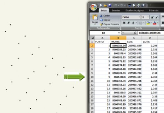
This routine generated for use in AutoCAD and its vertical applications, will allow you to insert the coordinates of points from a file of Microsoft Excel, with this routine it is not necessary to specify details related to the file to be imported, since through its interface you will have within reach the options Necessary to import the points as you wish.

To import the points, it is considered necessary that the point file to be imported has XLS extension (from versions prior to office 2007) or XLSX (version 2007 or later) And in the file the coordinates are formatted with the format: P, N, E, C, D, (Ptogether, NOrte, Este Cota DDescription), as shown in the following image:
It allows you to choose among 3 different types of ways to insert a point object in the read coordinate.
- The first is to choose to insert a AutoCAD Point entity (which is generated by the POINT command), remember that the display of a point in AutoCAD depends on the type of point display that you have defined with the DDPTYPE command.
- The second option consists of select a block stored in the drawing as a point to be inserted in the read coordinate, by default the routine creates a new block called “cg-point”, which can be used if there are blocks in the drawing or if there are no blocks in the drawing.
- The third option related to the style of point, Allows you to import a block from the hard disk, Remember that in this case the dimensions with which the block was created influence the visualization of the block at the time of insertion.
- With regard to point data (labels), iCe Lets you decide what you want to show, if you only want to display a Point, you will only have to select this option, the same for the text of the Dimension or the Description of the point. You can choose to display the 3 tag data or not display any.
Also You can control the number of decimal places in the inserted dimension text, The scale that will have the label, the rotation of the same whose base point is the location of the imported point and the separation of the label with respect to the point, these options can be stored with a name, so that you can call them according to the points that you will import.
All these options will allow you to import your points from an Excel file quickly and with a clear appearance, it is worth clarifying that the way the texts of the label of the point are seen does not depend on the routine, But the current text style of your drawing and the current layer.
Some time ago I published a routine developed by a user, which allowed to import the coordinates but from a text file but with many limitations, this time through this new command we will have more options to control the insertion of coordinate points.
The attached file also provides an example block that you can import, apart from a spreadsheet with the correct format that the command needs to import the coordinates without any inconvenience.
To use the routine you must do the following:
- Load the lisp file in AutoCAD.
- Enter the name of the command: ICE
- In the dialog box, specify the options that you think are convenient for importing points.
You can get the routine here
14. Import areas from a csv file to cross sections
This command allows you to import areas (default cut and fill) to cross-sections of terrain, areas to import must be in a CSV (comma-delimited) file, according to the attached sample file.
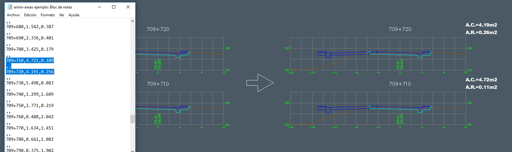
This command reads the progression located in the first column of the csv file and searches for the text with that same progressive in the drawing file, inserting its corresponding cut and fill area in the upper right of the cross section.
The suffixes inserted in the cut and fill area by default are: “AC=” and “AR=”, which can be manipulated by code, as well as the number of decimals and the height of the inserted text.
To use this routine you must do the following:
- Load the lisp file in AutoCAD.
- It establishes as current the layer that will contain the texts that will be inserted, for example: “Text-Areas”.
- Enter the name of the command: Arimx
- Select the SCV file that contains the areas to import
- Select the You want to insert Its corresponding area from the csv file, if you want to select all just press the key Enter.
You can get the routine here
15. List the routes of the images inserted in the drawing
 If you work with images, it has often been necessary to generate a list of them, including their location path, with this routine you can generate a list with the paths of all the images inserted in the current drawing.
This routine does not require the input of any option, simply call the command and immediately will be displayed in the AutoCAD command line, the list with the paths of the inserted images.
To use the routine you must do the following:
- Load the lisp file in AutoCAD.
- Enter the name of the command: lime
You can get the routine here
16. Replace a text with the current file path
This routine developed in Autolisp, allows us to update any text, with the path and name of the current file.
This is a good help when updating the letterhead of the plans with this information.
In the path obtained also includes the name of the current tab, if it is in the model space, it will show at the end of the path: model, otherwise it will show on behalf of the current tab.

To use this routine you must do the following:
- Load the lisp file in AutoCAD.
- Enter the name of the command: rue
- Select the text to replace with the value of the path of the current drawing, if you do not want to replace some text just press Enter To display the path on the command line.
You can get the routine here
17. Replaces a text selected by the current date with different output formats
With the help of this good routine we can replace any text, with the value of the current date.
The 8 command provides different types of formats for this date, ranging from a simple date type to a long format date type, where the name of the day of the current date is programmatically obtained with AutoLisp.
 You can select type entities text y Mtext, These will be replaced automatically by the current date with the format selected, the available date formats are those shown in the illustration, each one is identified by its number, which will serve to choose the format when requested on the command line Of AutoCAD.
To use this routine, you must do the following:
- Load the lisp file in AutoCAD.
- Enter the name of the command: RF
- Indicate by 1 number to 8, the date output format, you can enter the question mark (?), To view available date formats
- Select the texts you want to replace with the date with the selected format
- Press the key Enter To end the command and update the selected texts
You can get the routine here
18. ROUTINE LISP INVENTING OR TRANSPOSING SELECTED TEXTS
![]() Sometimes we want to invert the values of two texts, for example, that the text with the number 1346 becomes 1111 and vice versa, this routine allows us to transpose the values of the texts that are selected.
Sometimes we want to invert the values of two texts, for example, that the text with the number 1346 becomes 1111 and vice versa, this routine allows us to transpose the values of the texts that are selected.
To achieve this result, it suffices to indicate the two texts, one after the other.
Do the following to use this routine.
- Load the lisp file in AutoCAD.
- Enter the name of the command: between
- Select the two texts to be transposed.
You can get the routine here
19. ROUTINE REPLACING THE CONTENT OF A TEXT BY THE POINT OF INDICATED POINT
This new command obtains the dimension value (Y coordinate) of a given point and sets it as the content of the selected text.
This routine is very useful for example when working with terrain profiles and we want to obtain the height of a vertex and set it in one of the texts that indicate the terrain dimension, it can also be used when working with cross sections of terrain and You want to obtain the dimension value in the section axis and set it in text that will indicate that dimension value.

In this command you can indicate which scale will have the dimension to be set in the text, it is not the height of the selected text, but the scale that has the profile or section to indicate, if your profile for example is scaled 10 times In the vertical, you must set the 10 NC command to scale as a, so that the command, make the corresponding division and set the appropriate value in the selected text.
To use this routine, you must do the following:
- Load the lisp file in AutoCAD.
- Enter the name of the command: NC
- Indicate the scale of the quotas
- Enter the number of decimal places the text will have with the given dimension (3 by default)
- Indicates the point from which you want to obtain the quota and
- Select the text that will be replaced by the value of the quota obtained or if you wish you can press the key Enter To only display the quota obtained without replacing any text
You can get the routine here
20. ROUTINE THAT REPLACES TEXTS BY PROGRESSIVE AND ANOTHER WITH INDICATED COVERAGE BY ADDING A PREFIX OR SUFFIX
This command allows to obtain the values of progressive and dimension (values X and Y) of a indicated point and establishes them in the 2 selected texts.
In addition to each text it adds a prefix or a suffix, for example if a prefix is indicated for the dimension (Y coordinate) equal to “CT=”, when the elevation text is selected, the command will update the selected text by the value of the elevation obtained, plus the indicated prefix, for example “CT=236.42”, when the progressive text is selected, it will be updated with the value of the X coordinate obtained plus the suffix "0+", for example “0+10.0”.
This command comes with the prefixes for the progressive and already defined dimensions ("0 +" and "CT =") And can only be changed by modifying the source code, in addition this command can be modified if desired, so that a prefix and a suffix are added at the same time in the texts.
To use this routine, you must do the following:
- Load the lisp file in AutoCAD.
- Enter the name of the command: PC
- Indicates the point from which the values of the progressive (X coordinate) and the coordinate (Y coordinate)
- Select the progressive text
- Select the dimension text
The values of the texts will be updated with the data obtained
You can get the routine here
21. ROUTINE AUTOLISP TO ESTABLISH A SPECIFIC COTA AT AN INDICATED POINT
This is a routine made in Autolisp that allows us to set a dimension value (Y coordinate) at a given point.
This command requests data (points and values) and performs operations to obtain the final value to be set in the Y coordinate of the indicated point (changes the value of the coordinate of the UCS (Universal Coordinate System) at a point indicated by the entered value ).
To use this routine, you must do the following:
- Load the file into AutoCAD using the command APPLOAD or copying the file and pasting it in AutoCAD.
- Enter the command name: OS
- When prompted to indicate the dimension point, you must indicate a point on the screen (the point at which you want to set a particular dimension).
- The command will prompt you to enter the dimension value to set or select a text:
- Here you must enter the value of the dimension you want to have the Y coordinate at the indicated point, you can enter a value or you can select a text that contains the dimension value, the command will get only the numerical value in case the Also have some description.
To verify that the entered dimension has been established at the indicated point execute the command ID, indicate the point, and observe in the command line that the value of the Y coordinate is now with the value entered.
You can get the routine here
22. AREASX: ROUTINE LISP TO FIND AREAS BY CONTOURS
This command allows you to find areas indicating an internal point between objects or by selecting closed contours, this command shows the area obtained or otherwise sets it in a selected text.
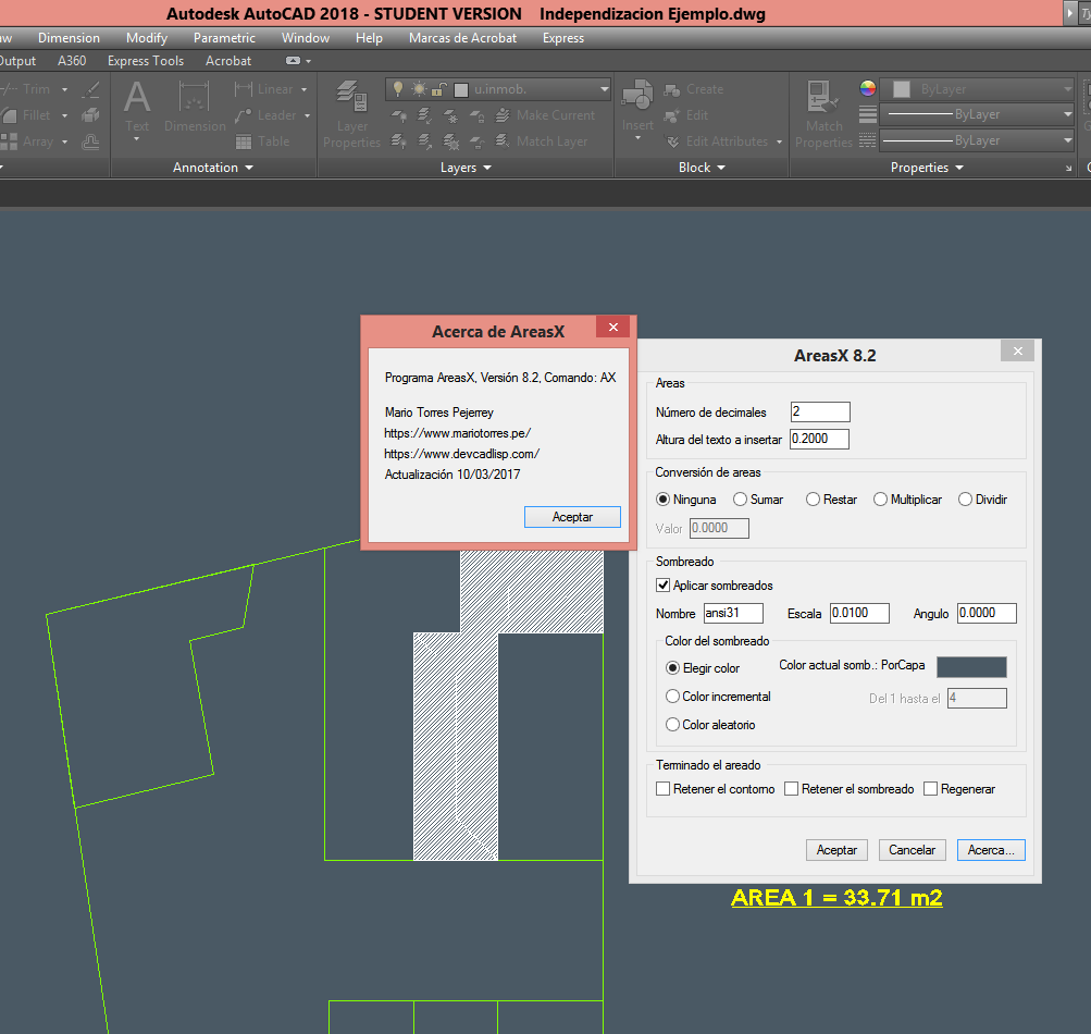
The Ax command has the following options:
Initial requests:
Specify an internal point of the area or [Select object / Options] :
Here you must indicate the internal points from which the area will be obtained, the other options are described below:
Select object: Instead of specifying internal points to find airs, you can select closed polygons to find your area.
Options: This option loads the Command Options dialog box, the dialog box is as follows:
Each option is described below:
Number of decimals: The number of decimal places the area will have (2 by default).
Height of text to insert: If you decide to insert a text with the area obtained, here is set the height that will have said text.
Conversions of areas: This option allows you to perform operations with the values of the areas found, each area is added, subtracted, multiplied or divided by a factor that must be specified in the lower part of this option.
The command shows if the conversion is active and which of the operations is carried out and with what value the conversion will be carried out.
This option allows you to customize the areas when the drawing is in different scales or in other drawing units.
Apply shading: This option allows each indicated area to be shaded to have a better view of the area that is being found, thus allowing to verify if it is correct (Enabled by default).
Name of the shading: Here you must indicate the name of the shading to be applied in the indicated areas (Solid default).
(Shading) Scale: Here the scale factor of the shading is indicated, this factor is variable according to the type of shading selected.
Color (shading): The color that the shading will have applied in the indicated areas.
Finishing the shading: The options below apply once the command application is terminated.
Hold contours: If enabled the generated contours are not deleted.
Hold shading: If enabled the generated shadings are not deleted.
Final Requests:
Specify an internal point of the area or [Select object / Insert area text / Options] :
Insert text area: This option allows you to insert a text with the obtained area instead of selecting one to replace it. The text with the area found has the default prefix: ” Area =”, this prefix can be modified in the program code.
Change text: This option is activated when the Enter key is pressed or the right mouse button is pressed, which will request a text to be selected, for example if there is a text with the following content: “AC=0.00m2” and through the command an area of 3.25 has been found, then the command will replace the text, updating it to “AC=3.25m2”. As you can see, AX replaces only the numeric values of the text to be replaced, so you can have area texts with different prefixes, for example: “AR=0.00m2”, “AM=0.00m2”, “Cutting area =0.00m2”, “My area=0.00m2”, etc.
Valid and invalid outlines:
Valid outline
To use this routine you must do the following:
- Load the lisp file in AutoCAD.
- Enter the name of the command: AX
- Indicate an internal point in the area you want to find (you have to make sure that the area to be found must be completely closed, otherwise the command will display an error message).
- Indicate internal points as many times as you need, the command will rage, accumulating (summing) all the airs found.
- Press Enter or right-click to end the command and set the area in an existing text.
You can get the routine here
Selecting Objects
23. Select all the entities of the layer of the selected object
This small routine performs the same as the previous one, the difference is that the name of the layer is not entered here to select the objects, but an entity is selected from which you want to obtain the name of the layer.
As in the previous routine, the selection of entities is not made visible, but it exists as a set of selected entities, so the selection mode must be indicated “Previous” to select the objects.

To use this routine you must do the following:
- Load the lisp file in AutoCAD.
- Enter the name of the command: ssl
- Select the object you want to get the layer name to select the other entities
- Make effective the selection of entities by means of the predictive mode
You can get the routine here
24. Remove internal or external objects from a selected polyline
Using this routine you can delete the objects that are in the inner or outer area of a selected polyline, if the option is indicated, the objects that are intersected by the polyline will be cut by the side indicated.
When it comes to removing objects outside the polyline, special care should be taken as This command deletes all objects outside the polyline.

The polyline to select Must be a closed polyline, otherwise the routine joins the last point of the segment with the first, Closing thus by means of an imaginary line the polyline and eliminating everything that is inside or outside that line.
The option cut as it is logical, only works with objects that can be cut manually, As for example, lines, circles, arcs, etc, blocks and other compound objects do not fit inside these objects that can be cut out.
With the lisp a sample file is attached So that the corresponding tests are done before using the command in final files.
To use the routine you must do the following:
- Load the lisp file in AutoCAD.
- Enter the name of the command: PolErase
- Select polyline Which will serve as an edge to delimit the objects to eliminate.
- Choose one delete objects option, you can choose the option: Window (it only deletes objects that are totally outside or inside that window), Capture (Removes objects that are even intersected by the edge of the polyline), delete and crop (As the name implies, it will erase objects that are inside or outside the polyline and trim objects that intersect the edge.
- Indicates a point on which side (internal / external) will erase or trim objects.
You can get the routine here
25. Allows you to select all the entities of the entered layer
It is a lisp routine that allows you to select all entities that are in the indicated layer, does not distinguish color or other property that may have the entity.
This routine is not case sensitive at the time of entering the name of the layer, so you can enter in any way, just that it is well written.
To use this routine you must do the following:
- Load the lisp file in AutoCAD.
- Enter the name of the command: sca
- Enter the layer name of the objects you want to select
- Effect the selection of entities by means of the mode Previuos
You can get the routine here
26. Copy the content of a text to another text
It is a routine made with the autolisp programming language, it allows us to copy the content of a selected text, and set that value in a second text to be selected.

- Load the lisp file in AutoCAD, using the comado Appload Or simply by copying the file and pasting it into AutoCAD.
- Enter the name of the command: RT
- Select the text, from which you want to get the value.
- Select the text, which you want to replace with the previously obtained value.
As you can see, the routine is simple, but it is very helpful when it comes to text editing.
It should be noted that the language used in this routine is clearly AutoLisp, in a new entry we will publish the same command but written in VisualLisp, in which we will observe that the size of the structure is further reduced.
You can get the routine here
27. Change the decimal number of a text without losing the original value
This lisp routine allows you to change the number of decimals of the selected texts without losing the original number of decimals, with that you can display a number for example with 2 decimals, but internally it will have a new property with its originally defined value.
This new property can only be accessed by this command, since it is not listed by the Properties dialog box.

The lisp allows you to change the number of decimals or obtain the original number of a text formatted earlier with this routine, So you know how many decimals you had originally If you want to reset the original values.
It is noteworthy that these original values remain Even though the file or AutoCAD has been closed, so you have the security that the original data of Your values will always be there, even in spite of restoring the original values to the texts.
This new command could be compared to the action of To change Excel decimals, But the only observation is that this property is internal and as we said earlier The Properties window is not ready to display extended date entities.
Particular consideration must be given to The selected texts are numerical texts, that is, they only contain numbers, since otherwise their value will be converted to “0.00".
To use the routine you must do the following:
- Load the lisp file in AutoCAD.
- Enter the name of the command: AREDE
- Choose one of the options you want to perform
- Select the (numeric) texts in which you want to perform the operation
You can get the routine here
28. Align several texts based on the first selected
Routine developed with AutoLisp that allows us to align several texts based on the first one selected.

The program allows you to align the texts vertically (columns) or horizontally (rows), for this you only have to select the first, which will serve as a basis for aligning the other texts.
It should be noted that the point taken as the basis for aligning the texts is the insertion point, if all the texts have the “Left” justification as the insertion point, all of them will be aligned with respect to this point and it will be a uniform alignment. If the texts have different justification, they will all be aligned with respect to their insertion point, which will cause the alignment of the texts to be inconsistent.
To use this routine you must do the following:
- Load the lisp file in AutoCAD.
- Enter the name of the command: lit
- Select the base text from which the alignment axis will be obtained
- Select the texts to align
- Done, the texts were aligned based on the first selected
You can get the routine here
29. Copy the height of a text and set it to other selected texts
This routine created in AutoLisp copies the height of a selected text and establishes it in the texts that are selected later, changing the height they had.
 For example, if you have 3 texts, the first one has a height of 3 and the next two have a height of 6 and you want the two seconds to also have a height of 3 instead of 6, it is enough to first select the text whose height is 3 and then the texts that have 6 height.
Do the following to use this routine.
- Load the lisp file in AutoCAD.
- Enter the name of the command: CA
- Select the text whose height is the one you want to copy or set.
- Select the texts you want to change the height for the first selected
You can get the routine here
30. Select a text and set the value obtained in the attribute of a block
This program made in Autolisp and Visual Lisp, allows to select a text, to copy the value of the content and to establish it (update) in an attribute that is part of a block.

That is, if we want to update an attribute of any block, for an existing text, simply select the text first and then the attribute and it will be updated according to the value of the selected text.
To use this routine you must do the following:
- Load the lisp file in AutoCAD.
- Enter the name of the command: cta
- Selects the text that contains the value to be copied.
- and finally select the attribute to change the measure
- The result is shown below:
As we can see, this command is very useful if we want to update a value of an attribute from a particular text.
You can get the routine here
31. Change the height of texts according to a percentage entered
This routine generated in AutoLisp allows us to modify the heights of the selected texts by changing them according to a percentage entered.

For example if you have two texts, one with height 0.5 and the other with a height of 1.00 and entering a percentage of 1.5, the heights of the texts will change by the following: 0.75 and 1.5 respectively.
This routine is very useful when it is required to make changes in the heights of many texts with different heights.
To use this routine you must do the following:
- Load the lisp file in AutoCAD.
- Enter the name of the command: ch
- Enter the percentage that will change the height of the texts, for example: if you enter 0.5, all texts will be reduced by half, and if you enter 2, all texts will grow double
- Select the texts you want to modify
You can get the routine here
32. ROUTINE LISP TO ELIMINATE THE CONTENT OF AN ATTRIBUTE OF A BLOCK
When you have a block with many attributes, it is very tedious to have to delete the content of many of them, usually double click on the selected attribute, wait for it to load the dialog and proceed to delete the content.

To avoid this tedious work, This little routine will relieve you a little of the time you spent in performing the task described above. With this command you only have to select the attributes that you want to delete the content.
You must verify that the texts that are in the block are attributes (sometimes confused between them), so that the routine works correctly. Mind you, this command Only deletes the content of the attribute, but not the attribute itself of the block.
To use the routine you must do the following:
- Load the lisp file in AutoCAD.
- Enter the name of the command: BCA
- Select the attributes of the block from which you want to delete its contents.
You can get the routine here
33. ROUTINE IN VISUAL LISP COPYING THE CONTENT OF A TEXT AND ESTABLISHING IT TO ALL SELECTED TEXTS
Some time ago I shared with you a routine that copied the value of a text and established it to another selected text, this time this routine will allow you to get the value of a selected text and will establish it to several texts that you select.
The use of this new command is very simple, you just have to select the text from where you want to copy the value and then you must select all the texts that you want to replace with this new value.

To use this routine you must do the following:
- Load the lisp file in AutoCAD.
- Enter the name of the command: RTN
- Select the source text of the value to be copied
- Select the texts that will be replaced by this new value
- Press the Enter key to end the command and update the texts with the new value
You can get the routine here
34. ROUTINE IN AUTOLISP THAT INCREASES OR REDUCES PROGRESSIVELY THE HEIGHT OF THE TEXTS
It is a lisp that contains two commands: Increase and Reduce, these commands allow to modify the height of the selected text, increasing it or reducing it of size according to the chosen command.
 The size change is done for each click made in the text and is done according to a factor indicated in the source code of lisp, this factor is 1.2. The initial height of the text is multiplied by 1.2 Each time you click on it or divide it between 1.2, depending on which command you have chosen.
For more information on how high the text is each time it is clicked, the routine displays the resulting height for each change in height made in the text.
This command is very useful when you want to increase or reduce heights of texts in proportion, without having to have a specified final height, only visual.
To use this routine you must do the following:
- Load the lisp file in AutoCAD.
- Enter the name of the command: AU (To increase) | RE (to reduce)
- Click on the text to increase or reduce the size as many times as you consider necessary
- Press the Enter key to end the command
You can get the routine here
35. ROUTINE LISP OBTAINING MEASUREMENTS OF SELECTED DIMENSIONS
The following routine allows you to obtain dimension measurements (dimensioned), the values obtained are displayed on the screen, which you can copy and paste for example in Microsoft Excel and each value will be pasted in a separate row.

To use this routine you must do the following:
- Load the lisp file in AutoCAD.
- Enter the name of the command: DimX
- Enter the number of decimals of the measurements to be taken (3 by default)
- Select the dimensions to get your measurements
- Press Enter to end the selection and display the values obtained
You can get the routine here
36. ROUTINE IN VISUALLISP THAT INCREASES THE VALUE OF THE NUMBERS ACCORDING TO A FACTOR
Routine in VisualLisp allows to increase the value of the numbers of the selected texts. This routine generated in VisualLisp allows to increase the value of the numbers of the selected texts (one by one) according to an indicated increase factor.
If the indicated value is a negative number the subsequent values will be a decrease of the initial value.

For example, if the initial value is the 1 number, and an increment value of 1 is entered, subsequent selected numbers will be incremented by one unit, the next 2, the next 3, and so on.
To use this routine you must do the following:
- Load the lisp file in AutoCAD.
- Enter the name of the command: inc
- Select the text with the initial value
- Enter the increment
- Select one by one all the texts you want to replace
- Press the Enter key to end the command
You can get the routine here
Lisp for topography and 3D
37. Convert 3DFace entities to ACIS solids
Some time ago I got this interesting lisp routine and although lately I have not used it, every time I have needed it has helped me enormously with volume calculations, this as a complement in the moments that civil 3D fails to give me the results I need .
It is a routine in which Selecting 3Dface objects, extruding them together and converting them into a single 3D Solid object, Its use is simple and just simply select the objects and the routine will do all the work.
![]()
For a greater appreciation of the changes that the routine makes in the objects, You need to have an 3D view, Otherwise in view of plant will not be observed the heights created in the 3D Solid, because the solid is created by projecting each selected face vertically “down” the current z-axis, To a plane and to a distance specified by the user.
To ensure that all parts of the mesh are generated as solids, This distance can not be zero, But the solid can be cut later if necessary to the required thickness, with boolean operations or solids editing operations. The resulting solid is created in the current layer.
If at the end of the union of the small solids, The operation stops or hangs Due to memory limitations, You can try to join them manually.
Notes to consider:
If adjacent faces do not have identical coordinates, There will be very small gaps or overlaps between the solids derived from them, which may be because AutoCAD can not be able to join the solids, showing the following messages:
- “Inconsistent containment of intersection curve.”
- “Inconsistent information in vertex and coedge coordinates.”
- “Inconsistent edge-face relationships.”
- “Inconsistent face-body relationships.”
If problems persist when generating the solid, you must copy a small distance and then merge the copies with the original to try to fill all the gaps in the 3DFace surface and try again until the problem is solved.
To use the routine you must do the following:
- Load the lisp file in AutoCAD.
- Enter the name of the command: F2S
- Select the 3D to convert to a solid
- Enter the height (down) that will have the solid from each vertex of the 3DF
- Enter the way to generate the solid: Automatic or Manual
You can get the routine here
38. Inserts dimensions in contour lines from its elevation
On several occasions you will have found that you have contours in a file, but these do not have their quota, through this routine, you can insert dimensions in the topographic level curve that you want.
The dimensions to be inserted are blocks with attributes, these blocks are created in a drawing in millimeters. So that you can use this lisp without problems, you must use the command “UNITS” (Units) define the units of the content to insert in “millimeters” (millimeters).
It is worth making clear that for this routine to insert the correct elevation to the contour lines, they must have an elevation (coordinate z> 0), since the elevation is obtained from the point indicated on a contour If the contour lines have elevation 0 (coordinate z = 0), that is, they do not have elevation, the routine will insert a text with that value.

The scale requested by the routine refers to the scale on which the drawing will be plotted, it is a referential value of the text size of the dimension to be inserted, you can try incrementing or decreasing this value until the dimension is inserted with the size of text you want.
This routine has 2 attachments: EL_TAG.dwg y EL_TAG2.dwg, it is the blocks with attributes explained above, these files can be copied anywhere, although it is recommended that they be in the same folder as the routine.
In order for AutoCAD to load these files, you must define the path of the AutoCAD location in the dialog box Options-> Support Files Search Path.
To use this routine you must do the following:
- Load the lisp file in AutoCAD.
- Enter the name of the command: CPE
- Indicates a point above the line of the level curve and in the place you want the dimension to be inserted
- Indicates another point to define the rotation that will have the dimension to insert
- You can continue inserting more dimensions indicated your insertion point, if you do not want to insert more dimensions, press the Enter key to finish the command
You can get the routine here
39. Draw the lines of cut or fill slopes
This routine draws the lines of the cut or fill slopes, these slope lines are necessary to indicate or represent the unevenness between the platforms.
In order to generate the slope line with this routine, 6 data must be entered which will allow the slope lines to be generated as expected.
The following information is required:
- Distance between slope lines (m): Here you must enter the separation between each line of slope.
- Select the polyline of the highest dimension: As the slope is a difference between two lines of edges, here it should be indicated that polyline is the one of the highest dimension.
- Select the polyline of the lowest dimension: The polyline of the lowest dimension must also be indicated.
- Cut or Fill?: The direction of the drawing of the beginning of the slope lines will depend on whether it is a cut or a fill, by default when pressing the Enter key, it will be taken as the fill value "R".
- Maximum slope line length: If the measure is less than the distance to the foot of the slope, it will be observed that the line does not intersect with the edge line of the slope foot, if it is desired that the slope the major slope foot reaches the intersection with the edge line of the slope foot, a larger value such as 200 or 500 should be indicated.
- Distance between talus benches: It is the Separation that the sidewalks will have.

You can observe the following graphs for a greater understanding of the definitions:
| Here a maximum length for the slope line of 5m has been indicated. | |
| Here a maximum length for the slope line of 200m has been indicated (the exact value is not important just to give an exaggerated value so that when it intersects with the edge line of the slope foot, it is cut automatically). |
To use this routine you must do the following:
- You must have as current the layer that will contain the lines of the slopes to be generated, for example: “Slope lines".
- Load the lisp file in AutoCAD.
- Enter the name of the command: tic
- Enter the data requested by the command.
You can get the routine here
40. Draw a line with a slope indicated
This routine allows you to draw a line with the slope that you indicate, just indicate the insertion point of the line and the slope that will have.

The slope is indicated by a value with respect to 1, for example: if you want to draw a line with a slope of 2: 1, only the 2 number should be indicated as slope for the line if the slope to be obtained is 1: 1.333, you must enter 0.75.
For further clarification, if slopes with the value of 1 first (1: x) are desired, divide 1 between the complementary slope (x).
To use this routine, you must do the following:
- Load the lisp file in AutoCAD.
- Enter the name of the command: DT
- Indicates the insertion point of the line
- Enter the slope that will have the line as explained above
You can get the routine here
41. Draw a line with an indicated slope
With this simple routine you can draw a line with the slope that you indicate, for this it is enough to indicate the insertion point of the line and the slope it will have.

The line is generated with a horizontal length of 10 units and a vertical length of the value of the slope indicated between 10.
To use this routine, you must do the following:
- Load the lisp file in AutoCAD.
- Enter the name of the command: LP
- Indicates the insertion point of the line
- Enter the slope that will have the line in percent (ejm: 12), without the percent sign
You can get the routine here
42. Calculate the cut and fill areas of cross sections
With this lisp routine you can find the cut and fill areas from a cross section that has a Natural Terrain line and a grazing line (section of the final road).
With this lisp routine you can find the cut and fill areas from a cross section that has a Natural Terrain line and a grazing line (section of the final road).
For this lisp to find the areas, you must make the selection of the terrain and grazing polylines and the command will ask for a point to insert the texts of the corresponding areas found.
To use this routine you must do the following:
- Load the lisp file in AutoCAD.
- Enter the name of the command: AREAS
- Select the polyline of the original path (Natural Terrain)
- Select the polyline of the road (Rim or Sub-Slider)
- Indicate point to insert the texts of the areas obtained
A sample CAD file is also included in the .rar file for further compression of the routine.
You can get the routine here
43. Insert the slopes of a longitudinal profile
This routine allows you to insert the slopes of a longitudinal profile (polyline or line) on the guitar. Simply select the profile (the polyline) and indicate a point that corresponds to the vertical location of the texts that indicate the slopes.

If it is a line, the command calculates only the endpoints, thus finding the slope, in the case of a polyline, the routine obtains each initial and final vertex and calculates the slope between them of all the segments of the polyline.
The text that indicates the slope obtained is of the type, for example: “P = 1.11% in 10.49 m” and as you know, this format can be modified to adapt to the way each one of you works.
As in the previous routine, the current text style should not contemplate a height, If you have an error and the slopes will not be inserted.
The scale indicated at the beginning of the routine is only for the sizes of the texts and does not influence the measures taken to process the slopes.
To use this routine you must do the following:
- Load the lisp file in AutoCAD.
- Enter the name of the command: Pop
- Enter the scale for the texts of the obtained slopes to be inserted
- Select profile to calculate slopes
- Indicates a reference point for inserting the texts with the slopes
You can get the routine here
44. Insert a mark in the vertices of a polyline
This lisp routine is an adaptation of the previous one and allows you to insert a mark in all the vertices of the polyline that you select, just select it.
The inserted mark is a drawing file (block) generated for a particular scale, but it is totally customizable, it can be edited like any drawing, it must only respect the center point of it (in this case the center of the circle of the block ).

In the source code of the file you can choose to insert a circle instead of the block, for that you only have to remove the comments of the line that contains this code and comment the line that inserts the block.
To use this routine you must do the following:
- Load the lisp file in AutoCAD.
- Enter the name of the command: IMA
- Select the polyline you want to mark its vertices
- Indicates the path and the name of the file to be exported
You can get the routine here
45. Obtain the slope of a selected line
This program developed in AutoLisp, allows to obtain the value of the slope of a selected line.

It should be noted that this command only works with lines, if you have a polyline it should explode or generate a line above the polyline.
To use this routine, you must do the following:
- Load the lisp file into AutoCAD.
- Enter the name of the command: TL
- Select the line from which you want to get the slope.
- The information obtained is the slope H: V.
You can get the routine here
46. 3 PACK ROUTINES FOR CONTAINMENT WALLS - PART 3: CREATING THE PROFILE FROM THE SECTIONS OF A WALL
By means of this routine you will be able to generate the profile (elevation) of a retaining wall, this profile can be made from the data of the cross sections of the walls, these data are: Progressive, Crown Dimension and Foundation Dimension.

The scale data requested by the command, does not refer to the vertical scale of the profile (the profile is generated with vertical scale equal to the horizontal) But the scale size for the profile texts (dimensions and other data).
To generate the profile, it is enough to first select the progression of the section, then the height of the crown and finally the height of the foundation.
You must take special care in selecting the data since if you do not select a text and click on the screen, the command will take it as having completed the selection of data to generate the profile.
Along with the routine is provided a CAD file, with wall cross sections, as an example to put the lisp routine into practice.
To use this routine you must do the following:
- Load the lisp file in AutoCAD.
- Enter the name of the command: MUP
- Enter the scale (size) of the profile texts (example: 75)
- Select the progressive text
- Selects the text of the crown dimension
- Selects the text of the bottom of the foundation
- Once you have completed the selection on all sections of the wall, press Enter And indicates a point at which the upper left corner of the crown of the wall profile will be generated.
You can get the routine here
47. 3 PACK ROUTINES FOR CONTAINMENT WALLS - PART 2: SIZE (COUNTED) OF THE SECTION OF A WALL
This routine allows you to dimension (dimension) a section of wall generated with the previously published routine (since it has the same design criteria), the result would be as the following image (the measurements vary according to the dimensions of the wall).
This routine asks for the scale for the dimensions that will be generated, This scale only refers to the separation between the lines of the dimensions, the size and shape of the dimensions depend exclusively on the current dimension style And this must be previously generated by the user for the scale being worked.

To generate the steps, proceed as in the previous routine for the generation of the wall, a point is indicated on the shoulder of the section of the road, on the side where the wall is needed and the height By means of the option to indicate a point in the bottom of the foundation of the wall.
It is worth mentioning that this routine only limits a section of wall generated with the routine of the previous postas it uses the same drawing criteria as the wall section, You can modify in the code the operations that calculate the points in case you want to apply for another type of wall.
To use this routine you must do the following:
- Load the lisp file in AutoCAD.
- Enter the name of the command: MUD
- Enter the scale for separations between dimension lines
- Indicates a reference point (P1 of the image) in the wall
- Indicates the meaning of the wall (Left or Right)
- Indicates a point at the bottom of the foundation of the section of the wall (P2 of the image)
You can get the routine here
48. PACK OF 3 ROUTINES FOR WALLS OF CONTAINMENT - PART 1: CREATION OF THE SECTION OF A WALL
This routine is the first of 3 that allow to generate walls of containment of the type of gravity, some time ago also we shared with you a routine that generated a retaining wall, this time the routine generates a wall with different design (measures).
It is to be remembered that the works of art of a road (walls, culverts, etc.), are not always of equal design for each work, this design is in function of many factors of the same area in which it builds them.
This routine allows you to generate a retaining wall with the following design criteria:
To generate it, you must indicate the shoulder of the slope Of the section of the road, on the side where the wall is needed, with the lisp the wall can be generated on any side, for that it is enough to indicate the direction (left or right).
With respect to height, This is defined using 2 options, The first is a defined height (H) and the second option is to define it by a dimension of the bottom of the foundation of the wall, This height can be indicated by a point on the screen, the program is responsible for calculating the height and all other measures from it.
The program is prepared to assume the two criteria of height of wall: The first criterion is a wall with constant height, Where the base of the foundation is not horizontal and The second criterion (the most used) is that the height of the wall is variable, Where the base of the foundation is horizontal and does not follow the slopes of the road.
The way to use this lisp will depend on each user, and for this the most convenient thing is that you can first generate wall plans without the help of any routine, in this way it will be much easier to understand the correct use of this lisp.
To use this routine you must do the following:
- Load the lisp file in AutoCAD.
- Enter the name of the command: MUS
- Indicates a point on the shoulder of the flank of the indicated side
- Indicates the direction of the wall (Left or Right)
- Choose how you will define the height of the wall (by height or height of foundation)
You can get the routine here
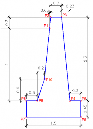
49. ROUTINE AUTOLISP TO DRAW A WALL OF CONTAINMENT
This lisp routine allows drawing a wall of gravity type for roads, the measurements with which this wall is drawn in this lisp are always the same (they are constant), the only measure that changes is the height of the wall.
The points with which this wall is generated are generated from the measurements of a particular wall design, if it is desired that with this lisp be generated walls with customized measures, they must change the measures that are written within the program .
Then you can see the following graph, which contains the points with which the wall is generated:
To use this routine you must do the following:
- Load the lisp file in AutoCAD.
- Enter the name of the command: MU
- Indicates the starting point of the wall generation
- Indicates the direction of the wall (Left or Right)
- Enter the height of the wall
You can get the routine here
50. ROUTINE LISP TO GENERATE THE PROGRESSIVE OF AN ALIGNMENT
This useful routine came to my hands some time ago and for those who want to generate simple alignments without the need to generate cross sections or longitudinal profiles of the same, can take advantage of this routine.
The routine has a dialog box interface which allow you to customize the final format of the progressives inserted in the shaft.
To use the routine you must have a polyline (alignment) and follow the following steps:
- Copy the 3 files downloaded into one of support paths of your AutoCAD
- Upload file lisp in AutoCAD (With APPLOAD).
- Enter the name of the command: Progressive
- In the dialog box, define the format of the progressives to be generated.
- Selects the polyline (alignment) in which these progressives will be generated.
- It indicates a point, which will become the starting point of the generation of progressives.
You can get the routine here
51. ROUTINE TO GENERATE A LONGITUDINAL PROFILE FROM POLLINES OF GROUND AND ROUGH
 This is one of the most complete routines to generate the format of a longitudinal profile. By simply selecting two 2D polylines (the terrain and flush), the routine generates the format of a profile with all the data that needs to be displayed.
In order for the generation of this profile to be successful, the polylines to be selected must be possible in 2D, otherwise an error may occur in its operation.
To use this routine you must do the following:
- Copy the downloaded 3 files On one of your AutoCAD support paths
- Upload file: profile profiles in AutoCAD (with APPLOAD).
- Enter the name of the command: profile
- In the displayed dialog box, click on the “Data” and click the buttons “Land"And"Slope” to select the terrain and grade polylines
- If you wish you can define Other data in the dialog box Before creating the profile (optional)
- Indicates the insertion point top of the profile to generate
You can get the routine here
52. ROUTINE IN VISUAL LISP TO ADD THE ARCOS MEASURES OF THE DRAWING
 This routine allows you to add the distances of all the arcs of the drawing or only those that you select, showing you the results of the addition in the line of commands.
This routine allows you to add the distances of all the arcs of the drawing or only those that you select, showing you the results of the addition in the line of commands.
To use this routine, you must do the following:
- Load the lisp file in AutoCAD.
- Enter the name of the command: Sumarque
- Select the arcs of the drawing you want to add, if you want to select all the arcs, press the key Enter before the request of the selection of arcs.
You can get the routine here
OTHERS
53. ROUTINE LISP TO IMPORT THE UCSS SAVED IN OTHER FILES
This interesting routine created with AutoLisp and Visual Basic for Applications (VBA), Allows you to import saved UCSs with a name from any file secondary to our drawing.
This tool is very useful If you work with planes that handle many UCS, we usually create the UCS in a first file and we have to do the same for the other files, with this routine, Simply create them in the first and we can then import them to any other file.
The routine behaves similarly to the Designcenter tool, except that it does not have the option to import UCS from other files. In the case of this routine Although it does not allow drag and drop, the results are as expected.
To use the routine you must do the following:
- Upload or add DVB and LSP files to Appload Startup Suite.
- Enter the name of the command: IMPUCS
- In the area Source Drawing, Click the button Select, to choose the drawing file from which you want to import the UCS.
- In the area UCSs Found, Select the UCS to import and click the OK button.
You can get the routine here
54. LISP ROUTINE THAT ELIMINATES THE INDICATED VERTICE OF A POLYLINE
It will have happened to you that in AutoCAD you have a polyline and you want to delete one of its vertices and to be able to do it you have to apply more than two commands.
With this routine Just enough that you indicate which vertex of the polinea you want to remove and arranged matter.
 For the routine to work correctly, at the point of indicating the point, This must be on the vertex to be eliminated and not a near point, for that you must activate the entities reference modes, such as Endpoint or Intersection.
To use the routine you must do the following:
- Load the lisp file in AutoCAD.
- Enter the name of the command: Evepol
- Select the polyline from which you want to delete a vertex.
- Indicates a point on the vertex of the polyline you want to delete.
You can get the routine here
55. ROUTINE THAT EXPORTS THE POINT OF COORDINATES OF THE VICTORIES OF OBJECTS 3DFACE
This routine written in Autolisp, is similar to the previous one, the difference is that this time, it exports the coordinates of the vertices of the 3Dface objects of AutoCAD, these coordinates are stored in a CSV file of Microsoft Excel, that is indicated for it .
 The export of vertex points can help you very much in case you have a triangulation with 3D face And you want to get their coordinates to recreate your coordinate point file.
The considerations also are the same as in the previous routine, in the case of 3Dface joined by the same vertices, Also if desired, consideration should be given to the Sort the coordinates and remove those that are duplicated.
The exported coordinates have the Format P, N, E, C (Point, North = Y, East = X, Dimension = Z) and as it is exported to a CSV file (separated by commas), when opening the file each value will occupy its cell independent and in an ordered way.
To use the routine you must do the following:
- Load the lisp file in AutoCAD.
- Enter the name of the command: E3D
- Select the 3D objects from which you want to export the coordinates of your vertices.
- Indicates the location and name of the CSV file in which the exported coordinates will be generated.
You can get the routine here
56. ROUTINE LISP TO COPY ENTITIES OF AN EXTERNAL BLOCK OR REFERENCE
Sometimes it is necessary to copy entities, but when they are inside a block, what we normally do is to exploit that block or perhaps to use the block editor, in order to have control of entities individually, select and copy them .

With this routine you will no longer need to exploit any blocks or use the block editor to copy any entity within it, Just load this routine and select the entities to be copied.
New objects created from the selection Appear above the originalTherefore If desired You must select them and move them to the desired position.
In this routine you can choose the option of That new objects can be created in another layer, which is chosen because by default the new entities are created in the current layer.
To use the routine you must do the following:
- Load the lisp file in AutoCAD.
- Enter the name of the command: CPL
- Select the features of the block you want to copy.
- If you want you can choose to change the layer in which the new objects are generated.
You can get the routine here
57. ROUTINE LISP TO TRANSFORM ARCHES OF A POLYLININE IN LINEAR SEGMENTS
This routine allows you to transform the arcs included in a polyline into linear segments, the length of each segment will be that you specify in the command options. The lisp takes the data from the vertices of the selected polyline, including the arc geometry and generates a new polyline with the new data.
The length of each new segment in the arc depends on the value entered, it must be smaller than the length of the smaller arc of the selected polyline, lisp will split the original arc into "n" segments until reaching its original length.
Optionally you can choose to keep the original polyline, which will cause a polyline to be created on top of it - or eliminate it.

This routine can be useful, for example, in the case that it is necessary to define points along a curve on an axis of a horizontal or vertical alignment.
To use the routine you must do the following:
- Load the lisp file in AutoCAD.
- Enter the name of the command: Artose
- Select the polyline from which you want to transform the curved segments into linear segments.
- Indicates the length of each segment that will make up the new linear “arc”.
- Choose what to do with the original polyline selected, if you choose to delete, you will only have the polyline with the curved segments transformed into linear segments.
You can get the routine here
58. AUTOLISP ROUTINE INSERTING POINTS AT THE DISTANCES SPECIFIED IN AN AXIS
With this routine you will be able to insert in a selected axis (polyline) points with their respective distances, the data of the insertion of these points, come from the manual digitization of distances or the reading of a file of distances (a file of example for a better understanding).
 This routine could be used for example in the case of the axis of a road, in some occasions it is necessary to locate an exact progressive in the axis (polyline), like for example the progressive one 23.76, you can manually do it but you take more time, with this routine you just need to select the axis, indicate the initial progression of that axis (usually with 0 value), and then enter the distance.
If you have too many distances to enter the axis, instead of typing them lisp provides the option of selecting a text file, within this text file will be the distances and the lisp will read them one by one, inserting them by a point on the axis (polyline).
The lisp also allows you to change the start of the axis Since the start is determined according to the start point that generated the polyline, if the lisp starts to put the distances by the end point that is not the desired one, use the option: “Change axis start".
Along with the routine is a CAD file, with a simple axis (polyline), as an example to implement the lisp routine.
To use this routine you must do the following:
- Load the lisp file in AutoCAD.
- Enter the name of the command: PP
- Choose how you want to insert the progressives: manually (1 × 1) or by reading a text file.
- Select the polyline shaft
- Enter progressive or initial distance from the axis (default is 0)
- Enter the progressive or distance to find (in the case of manual fingering, if a file reading was chosen this is not necessary)
You can get the routine here
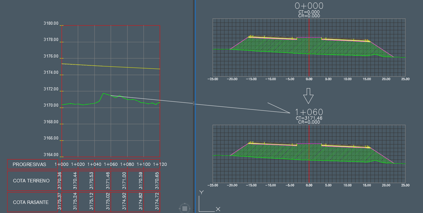
59. ROUTINE LISP THAT INSERT THE COORDINATES IN A PROFILE AUTOMATICALLY ACCORDING TO THE SPECIFIED SPACING
With this routine made with AutoLisp and VisualLisp, you will be able to insert every "n" meters the elevations of a selected polyline (natural or grazing terrain) in your profile format, the elevations will be inserted taking as reference a point indicated in the format.
In this command you can define the scale of the drawing, this scale does not refer to the vertical scale of a profile, but to the scale of the texts of the dimensions to be inserted, the dimension texts for an 1: 500 scale will be larger than those of an 1: 50 scale.
As well you can define the vertical scale of your profile, this data is important because it controls the values of the dimensions, in a natural terrain profile scaled in 10 times its size in the vertical will have the values of the dimensions also 10 times more than their actual size, so the command should to carry out the corresponding operations to transform the values of the quotas to the real ones.
Another value to enter and the one that defines this command, is the distance in which the dimensions will be inserted, the default value that this routine brings is 10, which means that the dimensions will be inserted each 10 meters horizontally from the indicated reference point.
After selecting the polyline that represents your profile (TN, Rasante, etc), the command will prompt you to indicate a reference point in your profile format, you must indicate this in a progressive whole, for example if your profile is from 0 + 000 to 100 + 000, you must indicate the point in the progressive 0 or 10 or 20, etc (according to each quoted the distance of insertion of the dimensions).
Remember in order for the program to obtain the corresponding dimensions, the profile must be correctly located, ie the dimensions are correct for the profile.
This chart will help you to better understand the options of this routine:
To use this routine you must do the following: (The default values are to follow the example with the attached CAD file)
- Load the lisp file in AutoCAD.
- Enter the name of the command: ICP.
- Enter the drawing scale for the dimension size: 850 (You can change until the size is appropriate)
- Enter the vertical scale of the profile: 1 (Vertical scale same as horizontal)
- Enter the distance between progressives: 10
- Enter the number of decimals, by default: 3
- Select the profile that you will limit (TN, Rasante, etc)
- Indicates the waypoint in the format of your profile (See graph)
You can get the routine here
60. ROUTINE LISP THAT ALLOWS TO OBTAIN PROGRESSIVE OR LENGTH IN AN INDICATED POINT
This routine developed in Autolisp and Visual Lisp, allows you to obtain the length or progressive of a polyline or axis and insert it into the drawing by means of an insertion point.
To do this you must select the polyline and indicate that the initial is progressive, you must verify that the command has obtained the starting point of the correct polyline (start of axis), if not, you can change the start of the axis with the option that Presents this command to you.
You can modify some default parameters from the source code, such as the height of the text to be inserted.
Note that your coordinate system must be positive, otherwise an error will be generated by indicating the progressive point or length to be obtained.
To use this routine you must do the following:
- Load the lisp file in AutoCAD.
- Enter the name of the command: OPR
- Select the axis polyline or enter the letter “C“, to change the start of the axis
- Enter the start (or initial) value of the starting point of the default polyline: 0.00
- Indicates the points in the line of which you want to get the length or progressive
You can get the routine here
61. LISP ROUTINE THAT MAKES DIFFERENT OPERATIONS WITH THE SELECTED TEXT (NUMERICAL)
It is a small but very useful lisp routine that allows you to obtain information on operations with selected texts, obviously these texts must have numerical values so that the calculations can be carried out, for example: “2.22”, “3.39” (without the quotes ), etc.
If among all the numerical texts the command Find a non-numeric text for example the word “dot”, will take this text as 0.00 value, So the results They would change.
The information provided by this command is:
- Count (Total number of selected selected numerical elements)
- NumberMaximum (The maximum value of all selected numeric texts)
- NumberMinimum (The minimum value of all selected numeric texts)
- Average (The average of all selected numerical texts)
- Amount (The sum of all selected numeric texts)
To get the results alone It will be enough to select one by one or by means of a window (Window) the texts from which information is desired.
To use this routine you must do the following:
- Load the lisp file in AutoCAD.
- Enter the name of the command: IV
- Select all the numeric texts from which you want to obtain the information
You can get the routine here
62. ROUTINE LISP THAT WALKS AND PRINT ALL LAYOUTS WITH ITS CURRENT CONFIGURATION
 This routine allows you to scroll through all the layouts and print each of them with the current page configuration you have, it is worth clarifying that the layout of the model space will not be taken into account.
The command runs through each of the layouts and if it verifies that it is the model space, it is skipped by continuing with the others, so if you want the model space to be printed, you only have to modify the command to Which is also taken into account and printed.
You can take advantage of the functionality of this command to, for example, insert letterheads, delete or add text in each layout, etc. The command does not print jobs in “background“, unless specified in the dialog box Options in the tab “Plot and Publish".
If you have many files to print and each one has many layouts, you can increase the functionality of this command by:
Create a file called Acad.lsp (if you do not already have it), in that file add the following lines of code anywhere in the same:
(defun s :: startup ()
(load “Loop through and print all layouts.LSP”) ;This is the name of the attached file.
)
The path is not indicated because it is understood that the path of the specified lsp file is added to the AutoCAD support directories (indicated in the options dialog), otherwise the line of code can be replaced by the (the full path of the lsp file to load is indicated):
(defun s :: startup ()
(load “C:\\CONSTRUCGEEK\\TUSLISP\\Loop through and print all layouts.LSP”)
)
To use this routine normally (without modifications) you must do the following:
- Load the lisp file in AutoCAD.
- Enter the name of the command: LPLOT
- You must wait until all print jobs are completed.
You can get the routine here
63. VISUAL ROUTINE LISP CUTTING THE TEXTS TO THE RIGHT OR LEFT ACCORDING TO THE NUMBER OF CHARACTERS INDICATED
This lisp routine allows you to trim selected texts, trim them to the right, left or both sides, that will depend on what the command is told.
For example if you have the initial text "0 + 580.00" and you tell the command to cut 2 characters to the left, the command will replace it with "580.00".
If you instruct the command to cut 3 characters to the right, the command will replace the initial text with "0 + 580".
Finally, if you tell the command to trim on both sides, 2 characters to the left and 3 to the right, the initial text will be replaced by "580".

As you can see, just indicate the number of characters to cut and select the texts and these will be cut as indicated.
To use this routine you must do the following:
- Load the lisp file in AutoCAD.
- Enter the name of the command: RET
- Indicates which side of the text will be trimmed [Left / Right / Both]
- Enter the number of characters to be cut on the indicated side (s)
- Select all the texts you want to cut
- Press the Enter key or right-click to make the replacement
You can get the routine here
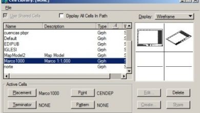


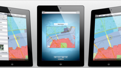

Hello engineer. Can you help me ? How to type coordinate grid in civil 3D 2024 please
Hello
Lisp درج شده، در راستای Z منتقل کند؟
به عبارت دیگر یعنی رقوم را واقعی کند ؟
There will be a routine that loads a cloud of points in PENCD format, separated by spaces or commas in Autocad 2015
or higher. Thank you
FOR WHICH TIVER DIFFICULTY EM BAIXAR AS LISP. I AM GOING TO BE ADDRESSED TO A SITE IN ESPANHOL E AÍ TÊM DE PROCURAR A VOSSA LISP EM ESPANHOL, I WILL NOT FIND NESSA PAGINA PROCUREM NO FIM DA PAGINA AS SETAS PARA PASSAR À NEXT PAGE ATÉ I WILL FIND YOU. DEPOIS É SÓ CLICAR NA VOSSA LISP, CLICK EM ATTACHED FILES E TAX OR APPLICABLE.
FOR WHICH TIVER DIFFICULTY EM BAIXAR AS LISP. I AM GOING TO BE ADDRESSED TO A SITE IN ESPANHOL E AÍ TÊM DE PROCURAR A VOSSA LISP EM ESPANHOL, I WILL NOT FIND NESSA PAGINA PROCUREM NO FIM DA PAGINA AS SETAS PARA PASSAR À NEXT PAGE ATÉ I WILL FIND YOU. DEPOIS É SÓ CLICAR NA VOSSA LISP E CLICK EM ATTACHED FILES E TAX OR APPLICABLE. I HOPE TER AJUDADO
Hello, I would like to know if you have any course or training to learn to program in Autocad. And also to create an app that helps me to count and identify a set of polylines
It runs for 2017 version or less. No for 2018 or 2019
boa noite .. gostaria of knowing to lisp 37. Converter entities 3DFace em solids ACIS works in all versões do auto cad?
thank yothank yo
I did not download your lisp
please sent me lisp
Where are the routines?
hello I would like to know how I can acquire those lips to extract the coordinates of a polyline and the one to obtain the polyline earrings
Thank you
HELLO
I work as a P&ID draftsman and I want to know how I can make the smart blocks that I have in an autocad plan export to Excel.
in the plans are:
Válvulas
line numbers
instrumentation
teams.
I want to extract that information and show it in Excel. if someone can help me please
Hi all,
ich suche eine Lisp, die es ermöglicht auf einer Polylinie an x-beliebiger Stelle eine Stationierung (also die Länge der Polylinie an dieser Stelle) anzuzeigen.
LG
Clear. We will send you an email regarding that functionality you are looking for in a lisp.
I look for lisp to make a gradient that is to say with a circle of a certain radius you have to cut a next level curve and generate a polyline from the origin and so on as you go to another place is for the design of a road and is morose copy the circles and draw the polygons thanks
Not like that. But I sent an email to an eclipse in lusp to tell you if he can do it
They have some routine to assign attributes to basic elements, not blocks, and these can be visualized in a dialog box on the screen.
Hey.
How do I download the lisp “Export Coordinate points to a CSV file”?
Thank you
GOOD NIGHT
I WOULD LIKE YOUR SUPPORT, I HAVE A PROBLEM MY AUTOCAD DOES NOT LOAD THE LIPS TO DRAW TECHNICAL DATA PICTURE (COORDINATES, SIDES, ANGLES)
Hello everyone, where I find more lisp
Hello everyone
is very good the list
very good contributions
A
ok
holaaaaaaaaaaaaaaaaaaaaaa
Hail, vorrei the Routine nominata AREASX, se è possibile.
Thanks in advance
Hello I would like to access the routine to put progrsivas to an alignment.
Thank you
I would like to send you a lisp routine that in recent versions does not work and in old versions if it worked, I hope you can correct it and / or improve it, to the mail that you indicate to me or when you send me the lisp routine.
Very good to all, I need the routine arcos_de_una_polilinea_en_segmentos_lineales.fas to be able to export from autocad to MIDAS GEN 2015 that no matter the arcs generated in autocad and I must break them into segments. Thank you so much. I'm from Cuba
Sou português e gostava, se possível, de ter a rotina “ROUTINE THAT REPLACES THE CONTENT OF A TEXT BY THE COTA OF THE INDICATED POINT”.
Thank you
there is a call
; Routine that exports coordinate points to a CSV file. 1.0 version.
; Format of the file of points that generates: P, N, E, C (Point, North = Y, East = X, Dimension = Z)
Look for it in the page of Mario Torrez
http://www.mariotorres.pe/recursos/rutina-lisp-para-exportar-puntos-de-coordenadas-a-un-archivo-csv
Please could you tell me where I can download your lisp routine "Export Coordinate points to a CSV file" because I have the topography of an area and I need to export it to csv or txt the points are entered as text (content is the height) and in the coordinate Z comes out zero, got it?
Please could you help me
I would like the lisp with the function of "Remove internal or external objects from a selected polyline", because in the article I can't find the download link.
INTERESTING ROUTINES.
Hi, I would like to know if there is a routine to obtain the number of objects and place them in text
Dear, I try to lower some routine and this warning comes out:
Not Found
The requested URL / forum / Routine-lisp-to-add-to-subtract-values-to-selected-text was not found on this server.
Additionally, in 404 Not Found error was encountered while trying to use an ErrorDocument to handle the request.
What am I wrong ?, 1000 thank you King
Hi if anyone knows any lisp that allows to draw poligono knowing, the length and angles, if anyone knows, the routine topo12 if they can send me ami mail juanpaulo_100@htomail.com, many thanks friends
Good data grax…. : p
good day, I would like to know routine for autocad 2014 if they had it to generate tables to parir of coordinates and design of highways
Thank you
regards
very useful for the development of engineering projects
Hello
sorry excuse me to help with a lisp to define a polyline with its km, I explain if I have a polyline with origin Dm of 100 start and a dm of end 1000, to be able to mark any point inside the polyline and I throw his dm and I leave stipulated.
now the dm of beginning and end will always be different for each project
If you could help me I would appreciate them as I work with this frequently and would be very useful in road projects.
regards
Greetings someone can help me with a lisp to be able to link a survey done with arbitrary coordinates starting from two points, then placed the original coordinates north and east and the quota left the same arbitaries from the two starting points for which I did With aling but quotas are changed
Hello you can see on this page:
http://acad.fleming-group.com/index.html
it explains how to access from your database and do things in it, it brings a set of lsp routines and a pdf that explains how to use them.
Greetings, Lola.
Good day, I would like to know if anyone knows any small routine or has some simple example of some small routine to create a dbf database and add data to it or delete from autolisp.
I hope they help me.
Thank you
Hello friends, I would like to know if anyone knows of a routine to measure the angles (or external) of a polygon and its distance and if it is not too much to ask them to export to Excel.
How do you write a .lsp routine that runs when a .dwg drawing is loaded and when it is recorded?
Thank you
I need help to see if anyone who knows lisp can save me.
I want to export from civil 3d all cross sections generated to text files, I just need to show the mileage, the distance to the axis, and the corresponding level.
Something like that
Km, Dist. To the axis, Dimension
Only that. Can somebody help me? I do not know anything about programming so I ask for help.
Let's see if I understood.
You say that with your lisp you export the coordinates to Excel
Have you put him at a distance? I do not understand that, I suppose it is in AutoCAD As dimension or function in the lisp?
But if you already have the coordinates in Excel, why not make a next column with a formula of pythagoras between the point and the next?
square root of ((y2 coordinate - y2 coordinate) squared + (x2 coordinate - x1 coordinate) squared)
HELLO GOOD DAYS, I WOULD LIKE TO HELP ME WITH A LISP. I EXPLAIN, I HAVE A SAMPLING PLAN, EVERY POINT POINTED WITH A LISP EXPORTS CORRESPONDED TO THE EXCEL, BUT NOW BETWEEN EACH POINT AND POINT, I PUT THE DISTANCE, NOW I WANT TO PASS THIS MEASURE BETWEEN POINT AND EXCEL, NOT TO BE 400PONTS AND THEIR DISTANCES, IS THERE ANY WAY? PORFAVOR, I WOULD SERVE MUCH AND THEN I WAS FASTER FOR WORK.
THANKS IN ADVANCE
To run Lisp routines, GeoCivil offers a fairly tuned tutorial.
http://geofumadas.com/5-minutos-de-confianza-para-geocivil/
Hello, I would like to know if there is any routine that transforms an autocad plane to another reference system for example from wgs84 to psad56
http://www.hispacad.com/foro/viewtopic.php?p=165851#165851
Attachment Routines for Drawing of long, cross profiles, Import and export of points through excel, various utilities, block library.
Within the manuals folder, there are the aids for the installation.
Inside the key folder will find the file for the activation.
Within the manual folder are the help files for the commands.
Note: for compaction reasons the updated manual has been removed and several images have been deleted in the attached help manual.
The updated manual can be requested by mail to
Vhcad@hotmail.com
In case the applications are useful to them, or to analyze for its own account the operation of the commands.
Use the pedit command
There is an option to insert vertices
How can I insert vertexes into a polyline.
Thank you