Georeferencing a CAD file
Although it is a basic topic for many, it frequently appears in distribution lists and in Google queries. It is no wonder that computer-aided design has been under an Engineering, Architecture and Construction approach for a long time, while the geospatial issue has had a relationship more oriented to land management. We cannot ignore that every day Both disciplines converge, to the extent that both AutoCAD and Microstation included georeferencing as a common feature from recent versions (AutoCAD 2009 up AutoCAD 2012 y Microstation XM Up to V8i).
Although a dwg or Days they can have georeference indicated in their programs, when they are opened by a GIS application that is not from the same manufacturer, it assumes that the file does not have a geographic location. In this, the georeference of CAD files is still a utility within programs of the same brand, for now. Nor will the GIS program do wonders if the file is on strange drives or in the wrong Cartesian location.
Let's see when, why and as with AutoCAD although it is the same with any other CAD program.
Why georeferencing in CAD has its complexity
For practical purposes, the plans of buildings we do without thinking about the georeference, and this has different reasons:
- We make plans looking for alignment with the screen. Although in the real world the building is rotated with respect to the geographic north, when drawing we are not very interested in that, we prefer to rotate the north symbol on the plane.
- Generally the plans are made for constructive purposes, so we are looking for ways to facilitate the creation of cuts and facades, as well as adapting to the creation of layouts Consistent with the geometry.
- While there are ways to create particular reference systems, it is not practical to work with an unreasonable orientation, at least when drawing the plans in traditional format and more when almost everything is designed orthogonal.
- When we need to do a placement plan, we usually call it an image, Orthophoto Or cadastral map, we rotate and climb for the purpose of detail but rarely consider working at once in that space.

"The true functionalism of architecture must be reflected mainly in its functionality from the human point of view. Technical functionalism can not define architecture."
Alvar Aalto
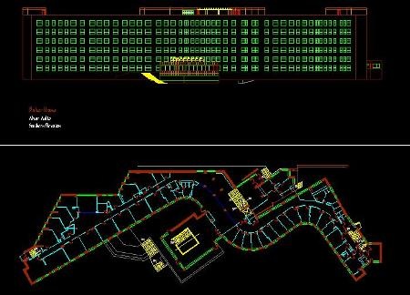
Designer of the building I'm using by example
Why geo-referencing is a necessity
The classic way of doing the planes has changed, the introduction of modeling gradually makes the programs adapt functionalities in which the 3D object is worked and the cuts or facades are a consequence of this.
Although this is a trend, in most situations plans continue to be made from a 2D plan. But we must not forget that this is irreversible, the need to make animations, the analysis of spatial variables and the BIM approach increasingly hammered in the CAD applications, As seen in Revit or ArchiCAD.

What it means to georeference.
To georeference, at least four aspects must be considered:
1. Set the units to meters.  If we are going to send to a system projected as UTM, it will be necessary that the units are meters. In many cases, the planes can be drawn using millimeters or even inches in the English system as units.
This is done with the command Units. And there we change the display from Architectural type to Decimal and in units from inches to meters. When making the change we notice in the status bar how the display form changes, however with this we have not changed the scale of the drawing, and if we measure a door that should measure 2.30 it appears as 92 which represents the inches that the 7 represents '- 7 ".
So you have to scale the drawing one factor, in this case the equivalent of converting inches to meters, would be 0.0254.
- The command is executed stairs, A reference point is chosen, the scaling factor is written and then enter.
2. Move the file to a UTM coordinate.
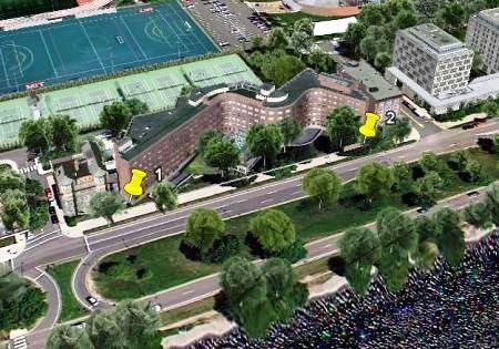
For this, known geographical coordinates are required, they can either be obtained with a GPS, from a georeferenced orthophoto, a cadastral map that has the building drawn or in the last case Google Earth with the risks that its precision implies. In this case, for example purposes I am using Google Earth:

1 point
X = 3,273,358.77
Y = 4,691,471.10
2 point
X = 3,274,451.59
Y = 4,691,510.47
These points are drawn with the command point.
- The command is typed point, Is enter, The coordinate is written in the 3273358.77,4691471.10 form and then it is done enter.
In the same way for the other point. Then all the drawing that we will move is selected:
- Command move, we click on the starting point that corresponds to the corner of the drawing without moving, and then we write the 1 coordinate; to not write it again we use the cursor arrow upwards and recover what we already typed in the previous step.
To do enter, the drawing will move to the area of interest as shown in the image. We will have to use the command Zoom extent to view. Or from the keyboard Z, enter, and enter.

If we do not look at the points well, you can change the format using the command Ddptype.
3. Rotate the drawing
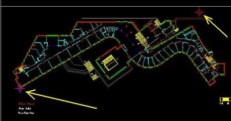
Now what is missing is to make the rotation of the drawing from the left node that we know is fine.
- It selects everything to be rotated, command rotate, The rotation axis is marked by clicking on the left point (magenta dot), the option is chosen reference, Click on the two points that define the rotation vector, first in the magenta point and then in the red point.

This action is similar to using the rotate command with three Microstation points, although here the horizontal is taken as the base.
What else involves geo-referencing?
With this, the file is not georeferenced. What we have done is place it in a projected coordinate system, in which its north coincides with the geographic north and the location with the UTM coordinates.
Always when calling it from a GIS application, the system will ask for the same data that implies projection and Datum. If we decide to do this With a GIS program Through a routine of rectification we must remember that it will only do so on the Model, layout Will be lost and xml properties when re-exported to dxf.
AutoCAD brings a tool called Geographiclocation, that we will see another day, as well as the option of georeference and reproject of Microstation.
4. External references
Doing this process could be only for temporary purposes of making a 3D animation, with which it would be enough to send the construction plan. If we want to do it as a definitive action towards complete existing projects, we must consider external references -That we use to save ourselves working with very large files or integrating different users- but that implies the separation of matching files in a workspace. If we do this with a file, those will have to be fixed as well.
Also the fact that sometimes the same file is copied inside the same Model, For printing purposes ... while still thinking about the loss of layouts.
"Someday anywhere, anywhere you will inevitably find yourself, and that, only that, may be the happiest or the bitterest of your hours."
Pablo Neruda
I know, part of the post is a can, the end is nothing short of desperate; But sooner or later it is necessary to do it, more if a client appears to us that wants to see something like this:


It would be a success if with this article I can solve my problem
Useful and simple. It doesn't deserve less than 10
The article is very good.
It's a problem and we all try to solve it.
Many times without success.
What is the source of the satellite image?
Format?
hello my question is I mostly work with civilian 3d geolocation, and I have 600 coordinate points, since I import the data to the civil 3d and I want to georeference it, the place then the satellite image in civil 3d is fuzzy there will be a command to be able to have more visibility of the place.
Hi very good
Dcggfxfg
Well I would not know to answer you, it would have to see if you are entering correctly the points of origin or destination.
Hello, I did the routine and it does not come out, it is assumed that when moving the drawing to the place where you need (with the coordinates), when moving to the new place that point should already have the correct coordinates, and mine does not give me Some coordinates and elevations that have nothing to do with the point I need, how do I do it?
Well, the first thing is to enter your georeferenced coordinates into a CAD file.
Then call the CAD file as a reference, and move it and rotate it according to the identified coordinates.
Hey.
I am writing to ask for help on this article. I really condes a lot with an exercise that I try to do but I do not get it, or I did not understand all the steps.
1. I have a file (cad) with a flat without georeferences.
2. I have an Excel file with 50 UTM taken directly in the plane terrain.
3. The objective is to georeference the plane and to be able to enter the UTM as points.
These points will then serve to continue working on the drawing, which will already be geo-referenced, but this is irrelevant, for consultation.
Thanks for a website so complete for those we like cad, and say that if someone can help me, be saying that I have to do or with an article so that I can do all the steps described.
Thank you very much
You change the configuration to UTM, it is in the general configurations.
The only thing I did not understand was how you got the points in X and Y, since in my google earth it gives me coordinates equal to these 25 ° 43'29.97 ″ N - 100 ° 22'39.55 ″ O, or if you could tell me how change them to points in X and Y, thanks ...
Thanks Mario.
What you mention is a reality. If there were a standard that could be done by the manufacturers ... although it is certainly not simple.
The CAD files should have a "universal" file, that is, that the georeferencing is recognized regardless of the manufacturer. Commonly I have to georeference DWG files of topographic surveys with an orthophoto, which many times ArcGIS does not recognize said georeference. Congratulations for the article, I found it very practical. Greetings.
Actually, I have not seen many iPad applications that allow to open a kmz file. What happens is that the kmz is a compressed file (such as a .zip or .rar), which contains within one or more kml and georeferenced or contained images within the same kmz file.
Try to see how they work: KMZ Loader, My Maps Editor, MapBox, POI Viewer, Map Editor, GPS-Trk
The best is GIS Pro, but it's worth a lot of money.
Another problem is that although some of these applications claim to support composite kmz, some run having Google Earth installed for iPad, and this is not available for all countries, especially in Latin America.
I congratulate you on your blog, I wanted to ask you a favor, if you could comment on how you can upload a map that was CAD and I converted it into a polygon (photo) to a KMZ file and I can not see it on my Ipad. I've tried everything and I can not. It seems very obvious, but I do not know how to do it. There are some applications that allow loading KMZ, but very limited (only positions), Thank you very much!
GOOD BLOG
Congratulations your blog is interesting continue like this.
Thanks for the article, very didactic !!