Transform a DGN file from ED50 to ETRS89
Often GIS users are faced with the challenge of transforming CAD data and reference systems. We say challenge because, in many cases, this transformation involves a meticulous work that allows us to finally keep the maximum possible information of the original data.
It is curious that this functionality comes with Microstation, but surely those who have done it there will know that the intuitive is not their specialty. This time I want to show using this visual aid that the Geobide Suite To explain how to do it we turn to Geoconverter, since this geographic format converter gives us the possibility to perform this process in a precise, simple, and Delivery to Italy takes one or two business days
As an example, we will take a DGN file with an ED50 reference system, and transform it to an ETRS89. In order for a conversion involving a file in the DGN format to be made more precisely than what is offered by default, it is advisable to take into account the following aspects:
1. Cell type elements
Geoconverter -> Input tab -> DGN Format -> Others tab -> option
Here we replace the virtual cell element by its actual definition present in the cell library

This option allows you to select the cell file (or also called cells), which are a similarity to the AutoCAD blocks in MicroStation in which the definition of the elements is stored to be able to take it to the output file.
As long as this library is not assigned, Geoconverter, by not having the definition of the blocks / cells, creates an equivalent block with a text with the original block / cell name in case a postprocess is to be replaced.
If defined from the beginning, the definition that comes in the file is inserted.
In the case of DGN, the cells are in files of type .CELL although they can be opened as normal dgn files, with the versions V8i.
In the case of DWG, it is in the seed where the blocks must be created.
2. Texts
In DGN file transformations we must bear in mind that when the justification of the original text is different from the down - left (JUST = LB ≈ 2), it is necessary to perform the extra configuration described below, since the size of the source Of the text modifies the position of the insertion point of the text.
Geoconverter offers two possibilities when recording texts from a DGN file. For this, it allows you to indicate how we want it to manage the insertion point of the text as well as the user point.
On the one hand we find the option to use resource files (* .rsc). This is a MicroStation-specific font format in which a file can contain various sources, each of which is identified by a number and a name.
Geoconverter -> Input tab -> DGN Format -> Resources tab

At the time of conversion, Geoconverter looks for sources in the files (* .rsc) indicated in the previous window. If you do not find a defined font file, use the specified font by default in your operating system settings. This can cause texts to be displaced.
If you define a font file (* .rsc), Geoconverter will know the font to be written to the destination file so that the text position is the same as the original file.
On the other hand, there is the option that allows you to redefine the insertion point of the text using MicroStation.
Geoconverter -> Input tab -> DGN Format -> Others tab -> option, here we redefine the text insertion point

This option executes the MicroStation program indicated in the table Location of MicroStatio"To calculate the actual size of the text font. This option is the most accurate since Geoconverter is able to interpret the MicroStation configuration (starting from the indicated route) and use the resource file described in it.
3. Configuration
Geoconverter allows to decompose different complex elements into simple entities.
On the one hand, it is possible to decompose cell / block elements into simple and independent entities.
Geoconverter -> Input tab -> DGN Format -> Configuration tab

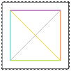
In the following example it can be verified that after decomposing the element represented in the figure 1 Image, the result are various entities represented in the figure 2 Image.
 |
 |
On the other hand, it is also possible to decompose the geometry of elements with curves into single segments.

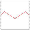
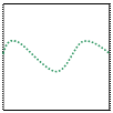
The following example shows in the figure 1 Image the mode in which a curved element is displayed in a CAD format. In the image 2 the vertices that make up the curve of the figure Image 1 are observed. Figure 3 can verify that Geoconverter enters the number of vertices needed to maintain the geometry of the original element curve.
 |
 |
 |
4. Colors
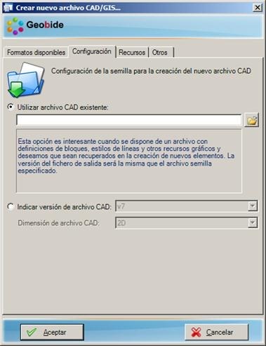
At the time of creation of a CAD file, it is possible to specify a seed file to be used in the transformation. This file contains information about configuration parameters such as work units, scaling, ...
It should be noted that the definition of the color palette of the DGN files is defined in the seed file, whereas in the DWG files, this palette is fixed.
Geoconverter -> Output tab -> DGN Format -> Configuration tab

If no seed file is specified, Geoconverter uses a generic file that comes embedded with the application. The best thing is to specify it to obtain a result adjusted to the need of each situation.
More information Www.geobide.es


